Low impedance
A low impedance sound system is realised by direct connection between amplifier and speakers, without the need for the use of transformers in the equipment. The load impedance needs to be matched correctly so that the power transfer from the amplifier to the loudspeakers is adequate. The speakers are combined in series or parallel so that the resulting impedance matches that of the amplifier output terminals. To achieve maximum transfer, the resulting impedance must match the minimum load impedance of the amplifier.
Z AMPLIFIER OUTPUT ≤ Z SPEAKERS INPUT
The output power of the amplifier must not exceed the total power supported by the speakers. If the RMS power of the amplifier exceeds that of the speakers, the speakers may be damaged.
The total power of the speakers connected to the output must be equal to or greater than the power delivered by the amplifier.
P AMPLIFIER OUTPUT ≤ P SPEAKERS
A low impedance installation is one that is characterized mainly by:
- Speakers must be the same type and match both in power and impedance.
- The number of speakers must be any from 2 to the power 2 [1, 2, 4 or 8] .
- The installation is not expandable when designed for a fixed number of speakers.
- They allow short cable runs as interference appears at medium and long distances.
- The speakers are in most cases high power with good bass response.
Typical low impedance facilities are discotheques, event halls, live concerts, recording studios and domestic applications.
Pair of speakers in series connection
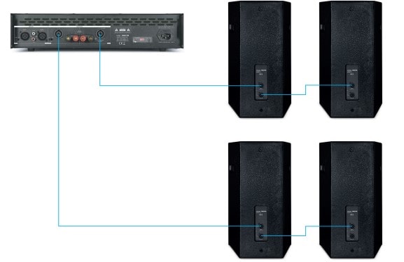
In a series speaker connection, the current flowing through each speaker is the same and is that supplied by the amplifier. In contrast, the voltage supplied by the amplifier is then dealt between each speaker. The impedance of each speaker would be equal to the sum of the impedances of each speaker.
EXAMPLE 1:
There are 2 speakers connected in series with an impedance of 8 Ω each. The total impedance is therefore the total sum of the speaker impedances, i.e. ZTOTAL=16 Ω.

Pair of speakers in parallel connection
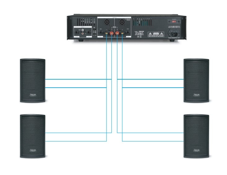
In a parallel speaker connection, the voltage applied by the amplifier to each speaker is the same, while the supplied current is divided between each speaker. The inverse of the total impedance of the connection is equal to the sum of the inverse impedance of each speaker. An easy way to calculate, as long as the speaker impedance value matches, is to divide the speaker impedance value in half.
EXAMPLE 2:
There are 2 speakers connected in parallel with an impedance of 8 Ω each. The total impedance is therefore half the value of the speaker impedances, i.e. ZTOTAL=4 Ω.
Mixed speaker connection (series / parallel)
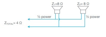
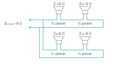
When more than 4 speakers are to be used, it is necessary to make series/parallel combinations to adapt the impedances. It is typical to find a parallel mixed connection of 2 speakers connected in series with 2 speakers connected in series.
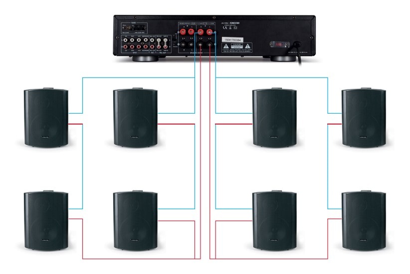
EXAMPLE 3:
There are 4 speakers connected 2 to 2 in series and each pair in parallel with each other. Each speaker has an impedance of 8 Ω. The total impedance is therefore ZTOTAL= 8 Ω.
Connection example
When more than 4 speakers are to be used, it is necessary to make series/parallel combinations to adapt the impedances. It is typical to find a parallel mixed connection of 2 speakers connected in series with 2 speakers connected in series.
| POWER AMPLIFIER | POWER | IMPEDANCE |
|---|---|---|
| Power stage 1 | 150 + 150 W 100 + 100 W |
@ 4 Ω @ 8 Ω |
| Power stage 2 | 400 + 400 W 300 + 300 W |
@ 4 Ω @ 8 Ω |
| Power stage 3 | 675 + 675 W 450+ 450 W |
@ 4 Ω @ 8 Ω |
Pub Zone 1: To connect the 2 100 W RMS speakers, power stage 1 will be chosen, fulfilling that:
Z AMPLIFIER OUTPUT ≤ Z SPEAKERS INPUT
A speaker with impedance 8 Ω shall be connected to channel L of the power stage with impedance 8 Ω. In the same way, the speaker will be connected to channel R.
P AMPLIFIER OUTPUT ≤ P SPEAKERS
A 100 W RMS power speaker shall be connected to channel L of the 100 W RMS power amplifier. In the same way, the speaker will be connected to channel R.
Pub Zone 2: To connect the 4 250 W RMS speakers, power stage 2 will be chosen, fulfilling that:
Z AMPLIFIER OUTPUT ≤ Z SPEAKERS INPUT
A series association of 2 loudspeakers with impedances of 8 Ω shall be connected to channel L of the power amplifier with impedance 4 Ω, the resulting impedance being 4 Ω. In the same way, the speaker connection will be made to the R-channel.
P AMPLIFIER OUTPUT ≤ P SPEAKERS
To the L channel of the 400W RMS power amplifier, a series association of 2 loudspeakers with 250 W RMS power shall be connected, resulting in 500 W RMS power. In the same way, the speaker connection will be made to the R-channel.
100 V line
A 100 V in-line sound system, also known as a constant voltage distribution system, is realised by connecting amplifier and loudspeakers, both with transformers, one at the output of the amplifier and one at the input of the loudspeaker, thus allowing the signal to be sent at high voltage [100 V].
The 100 V line output is used when the distance between loudspeakers and amplifier is large (greater than 30 m and up to several kilometres) and when a large number of loudspeakers are to be installed. The use of these transformers avoids power losses on the transmission line.
This method eliminates the calculation of impedances and complicated series/parallel speaker set-ups. In this way all loudspeakers are connected in parallel and the power can be chosen according to the loudspeaker requirements.
For the correct balance of the installation, the sum of the loudspeaker power must be equal to or less than the RMS output power of the amplifier. If the power sum of the speakers is greater than that supplied by the amplifier, this may cause the amplifier to malfunction.
P SPEAKERS ≤ P AMPLIFIER OUTPUT
EXAMPLE 4:
There are 10 W RMS 6 speakers, getting a total power of P TOTAL = 60 W RMS, for its connectionto an amplifier of 60 W RMS.

EXAMPLE 5:
There are 6 speakers, 1 x 30 RMS, 2 x 20 RMS, 2 x 10 W, 1 x 5 W RMS giving a total powerof P TOTAL 95 W RMS, for connection to a 120 W RMS amplifier.

