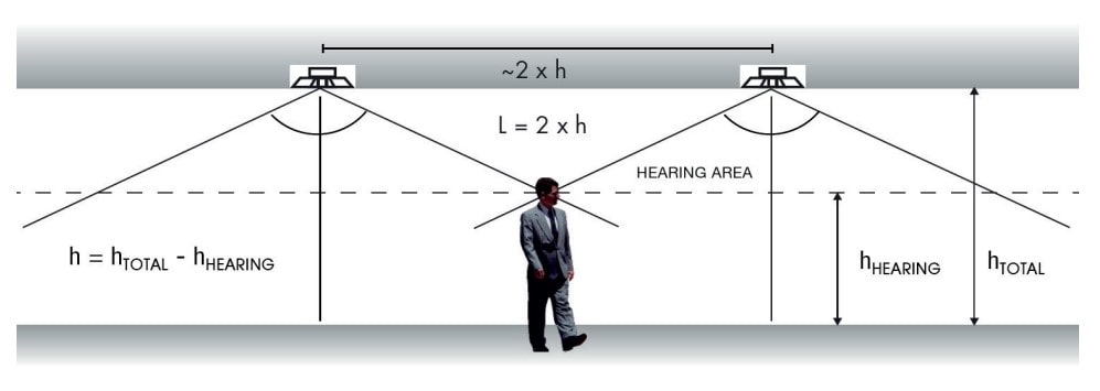
As a rule of thumb, for speakers placed in the ceiling at a height between 2 and 4 metres, the sound points should be spaced approximately twice as far apart as the height of the speaker from the listening plane. The approximate coverage area per loudspeaker should be around 25-30 m2. Typical power ratings are 3 W, 6 W, 10 W RMS.
Speaker arrangement
Ceiling speakers and baffle-type surface speakers
EXAMPLE 6:
You want to cove a room of dimensions 20 x 10 x 3 m with speakers of 120° of coverage angle. Since the floor area will be 200 m2, approximately 6 to 8 ceiling speakers will be required for each to cover an area of 25 m2 – 30 m2. In this case, ideally 8 speakers would be used.
The same space with a surface area of 200 m2, but a height of 4m m, will require less number of speakers as each will cover more area. In this case, 6 speakers would be ideal.
If the angle of coverage increases, so will the coverage area.
In-wall baffle-type surface speakers should be placed on the perimeter of the enclosure, with an appropriate orientation to respect the sense of origin of the sound. It is usually common to separate the speakers about 10 m. Ç
Each speaker shall cover an area of 30-35 m2. Typical power ratings are 8 W, 16 W, 32 W RMS.
Sphere type speakers
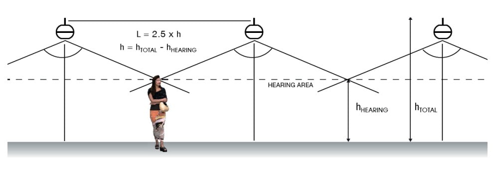
For sound spheres, the spacing shall be approximately 2.5 times the height at which the speaker is located, being between 4 and 7 metres. This standard varies slightly with respect to ceiling speakers, as the area covered is somewhat larger. The approximate coverage area per speaker should be around 80-100 m2. Typical power ratings are 20 W, 30 W, 50 W RMS.
Column type speakers
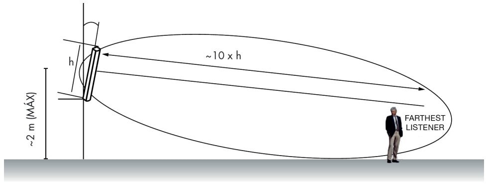
This type of speaker is much more directive than the baffle-type surface speakers, and the directivity of the sound depends on the height of the column.
The speaker must be directed toward the audience and the placement height is usually approximately 2 meters up to the middle of the sound column.
Sound columns can be analogue or digital.
Traditionally, analogue sound columns are only used in venues where the floor plan dimensions do not exceed 10 m in width, using two rows of loudspeakers on each wall, spaced 6 m apart. If the dimension is less than 5 m, a single row is used.
Digital columns are now used for higher quality. 1 or 2 must be placed in the speaker zone which will allow the sound to be focused in the audience area at a distance of 30-40 m. In this way, with 1 or 2 columns it will be possible to cover approximately an area of 300-600 m2, being equivalent to an installation with 6 or 12 analogue columns. In addition, unlike analogue columns, they are active, so there is no need to connect them to a power amplifier.
EXAMPLE 7:
A religious centre of dimensions 40 x 15 x 6 m is to be covered with column speakers. Since the surface area will be 600 m2, approximately 10-12 columns will be required and 5 or 6 will be required along each 40 m wall Each will cover an area of 50-60 m2.
The same 600 m2 religious centre will be able to equip 2 digital columns replacing the analogue columns solution. Each column will cover an area of 300 m2.
Projector and exponential type speakers
When it comes to sound projectors and exponential speakers, the range is both highly dependent on directivity and power. The recommended separation is approximately 15 to 20 meters for projectors and 25 to 40 meters for exponential speakers. Typical power ratings are 20 W, 30 W, 50 W, 60 W RMS.
Projector type speakers should be used for speech and piped music, and exponential-type speakers should be used for speech only.
Wiring selection
In 100 V line installations, the speaker connection is done in parallel, on one or more lines depending on the needs. The main line, connected to the amplifier terminals, is called the distribution line. This line can be the only line or it can be the distribution line to which one or more terminal lines are connected.
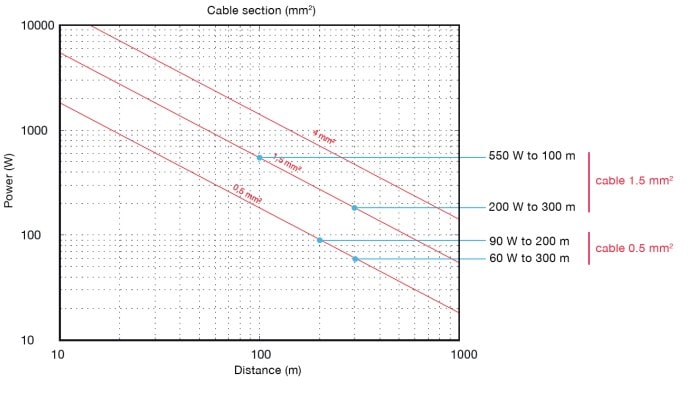
Graph I shows the maximum transmit power W (in watts) for three typical cable sections (in mm²) and the maximum transmission line distance.
The power (W) of the terminal lines shall be the sum of the unit powers of the connected speakers. In distribution lines the power (W) shall be the sum of the powers of the terminal lines connected to each line.
In any case, a minimum section of 0.5 mm² is recommended.
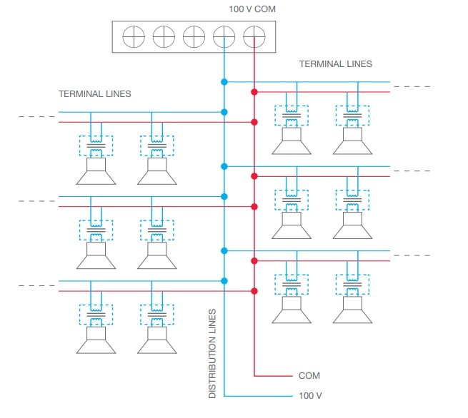
FIGURE 1
Variation of sound pressure level (SPL) depending on power and distance
The sound pressure level (SPL) provided by a speaker varies according to the electrical power (P) delivered to that element according to the following formula:
SPL (dB) = SPL (1 W) + 10 · log (P)
Where P is the power delivered to the speaker.

In an equivalent way, the sound pressure level decreases as a function of distance (d) as follows:
SPL (dB) = SPL (1 m) − 20 · log (d)
Where d is the distance to the listener.

For sound pressure level calculations in public address installations both formulas are generally applied, so we can combine them as follows:
SPL (dB) = SPL (1 W/1 m) +10 · log (P) − 20 · log (d)
As a general rule we can set the SPL level to increase by 3 dB each time the power doubles and decrease by 6 dB each time the distance doubles.
| PRACTICAL REGULATIONS |
|---|
| Power x 2 = +3 dB |
| Distance x 2 = -6 dB |
